Que recherchez-vous ?
Un contenu sur ce site
Une personne sur l'annuaire
Une formation sur le catalogue
Un contenu sur ce site
Une personne sur l'annuaire
Une formation sur le catalogue
Context
HVOF is part of the thermal spray coating techniques and consists in spraying molten or semi-molten particles onto a substrate surface.
The primary mechanism of adhesion is the mechanical interlocking or anchorage. Prior to the coating deposition process, the surface of the substrate is subjected to a grit blasting of alumina particles in order to create roughness and therefore favor the coating particles anchorage. But the grit blasting has also a very strong impact on the mechanical properties and microstructure of the coating.
Nanoindentation is used in order to obtain the mechanical properties of both the coating and the substrate while microscopy techniques such as AFM and SEM are used to observe the microstructure of the indented zone. We use the so-called nanoindentation cartography method which consists in reconstructing, using an interpolation algorithm, a map of hardness and Young modulus from a regular array of indents performed on the materials.
The coating is a cermet material made of chromium carbides Cr3C2 (80%) embedded in a NiCr metallic binder (20%). The coating is deposited onto a 17-4PH stainless steel which was grit blasted with alumina particles prior to the coating deposition.
Results
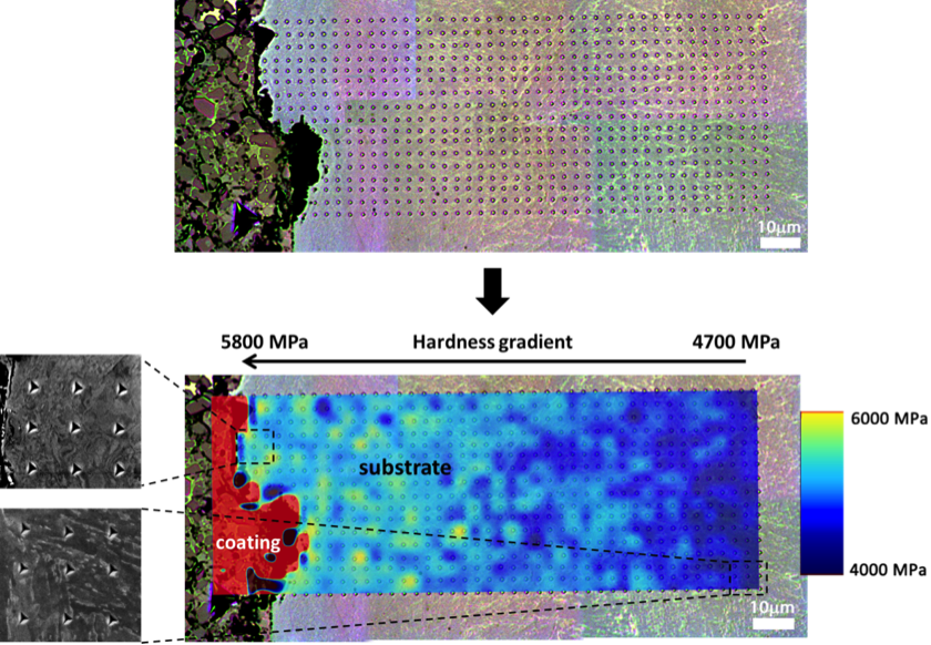
Figure 1 shows the mapping of hardness superimposed to the optical microscopy image of the array of indents. The array is made of 17*45 indentations. The hardness of the steel substrate increases from 4700 MPa at 110um away from the interface up to 5800 MPa at the interface. The hardness values correspond to an average of 17 indents carried out at each distance from the interface. So an increase of 23% is observed. The young modulus is also investigated and is constant throughout the substrate surface with an average value of 220GPa.
Additionally as shown on figure 1, microstructure observations obtained in a SEM reveals different microstructures depending on the distance to the interface. A first image away of interface shows the regular lath martensite microstructure and a second observation at the interface reveals a fine grain microstructure on a 10um band.
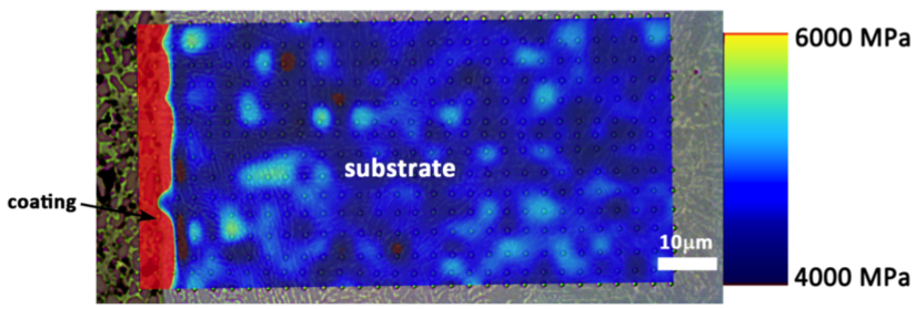
The change of microstructure associated with an increase of hardness is a consequence of the grit blasting applied prior to the deposition process. Indeed, the same experiment performed on a sample with the coating deposited on a polished substrate (hence without grit blasting) shows constant hardness throughout the substrate thickness (figure 2).
So the grit blasting has a strong impact on the hardness and microstructure of the substrate. It is very important in order to understand the adhesion mechanisms because even if it has a positive effect by creating roughness and hence favoring the mechanical anchorage, it also seems that the grit blasting can have a detrimental impact:

